Copper tubes are among the most widely used materials in HVAC, refrigeration, heat exchanger, and air conditioning systems. Thanks to their excellent thermal conductivity, corrosion resistance, pressure tolerance, and long service life, copper tubes have become the preferred choice for engineers and manufacturers worldwide.
Selecting the correct copper tube size is essential for maximizing system performance, reducing pressure drop, and ensuring efficient refrigerant flow. This guide provides a complete copper tube size chart, dimensional references, and selection guidelines for HVAC and refrigeration applications.
What Are Copper Tube Dimensions?
Copper tube dimensions are generally defined by three key measurements:
Outside Diameter (OD)
Outside Diameter is the external diameter of the tube and is the primary dimension used when selecting fittings and accessories.
Wall Thickness
Wall thickness determines the tube’s pressure resistance and mechanical strength.
Inside Diameter (ID)
Inside Diameter affects refrigerant flow capacity and pressure loss throughout the system.
The formula is:
ID = OD − (2 × Wall Thickness)
For example:
OD = 12.70 mm
Wall Thickness = 0.81 mm
ID = 12.70 − (2 × 0.81)
ID = 11.08 mm
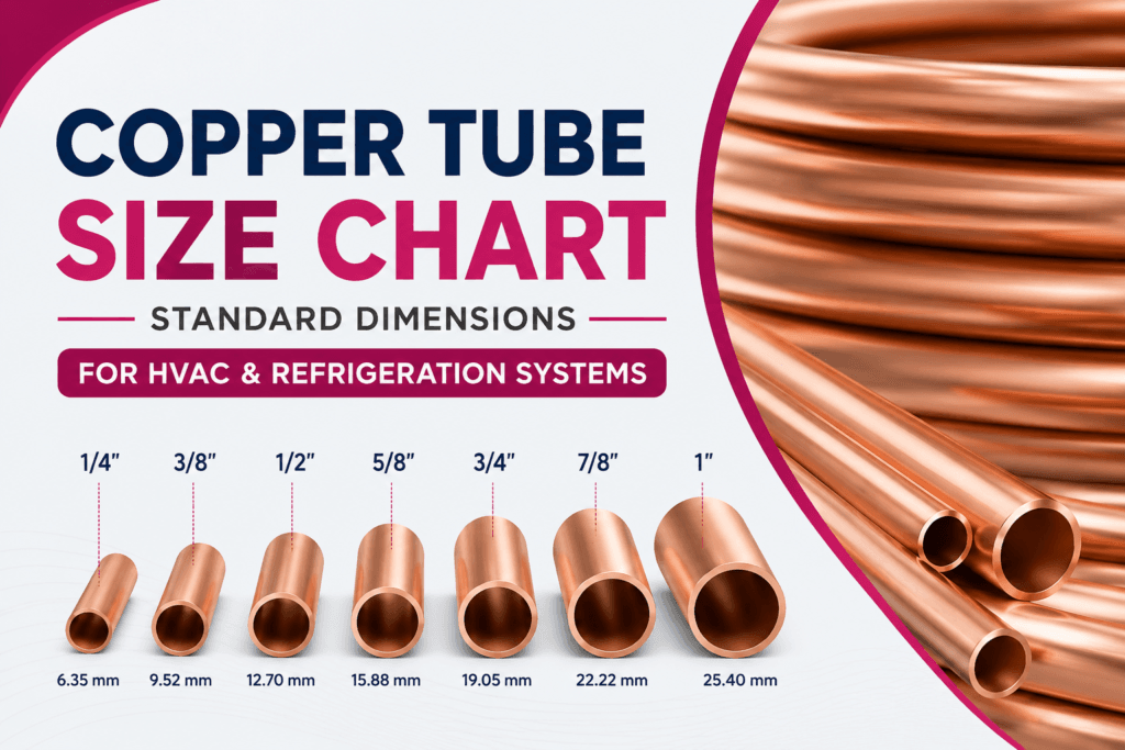
Standard Copper Tube Size Chart
The following table shows the most commonly used copper tube sizes in HVAC and refrigeration systems.
| Nominal Size (inch) | Outside Diameter (OD) mm |
|---|---|
| 1/4″ | 6.35 |
| 5/16″ | 7.94 |
| 3/8″ | 9.52 |
| 1/2″ | 12.70 |
| 5/8″ | 15.88 |
| 3/4″ | 19.05 |
| 7/8″ | 22.22 |
| 1″ | 25.40 |
| 1-1/8″ | 28.58 |
| 1-1/4″ | 31.75 |
| 1-3/8″ | 34.93 |
| 1-1/2″ | 38.10 |
| 1-5/8″ | 41.28 |
Copper Tube Dimensions Chart
| OD (Inch) | OD (mm) | Typical Wall Thickness (mm) | Approx. ID (mm) |
|---|---|---|---|
| 1/4″ | 6.35 | 0.80 | 4.75 |
| 5/16″ | 7.94 | 0.80 | 6.34 |
| 3/8″ | 9.52 | 0.80 | 7.92 |
| 1/2″ | 12.70 | 0.81 | 11.08 |
| 5/8″ | 15.88 | 1.00 | 13.88 |
| 3/4″ | 19.05 | 1.00 | 17.05 |
| 7/8″ | 22.22 | 1.14 | 19.94 |
| 1″ | 25.40 | 1.27 | 22.86 |
| 1-1/8″ | 28.58 | 1.40 | 25.78 |
| 1-1/4″ | 31.75 | 1.40 | 28.95 |
| 1-3/8″ | 34.93 | 1.60 | 31.73 |
| 1-1/2″ | 38.10 | 1.60 | 34.90 |
| 1-5/8″ | 41.28 | 1.80 | 37.68 |
Actual dimensions may vary according to manufacturing standards and wall thickness requirements.
Copper Tube Size Conversion Chart
| Inch | Millimeter |
|---|---|
| 1/4″ | 6.35 mm |
| 5/16″ | 7.94 mm |
| 3/8″ | 9.52 mm |
| 1/2″ | 12.70 mm |
| 5/8″ | 15.88 mm |
| 3/4″ | 19.05 mm |
| 7/8″ | 22.22 mm |
| 1″ | 25.40 mm |
| 1-1/8″ | 28.58 mm |
| 1-1/4″ | 31.75 mm |
| 1-3/8″ | 34.93 mm |
| 1-1/2″ | 38.10 mm |
Common Copper Tube Sizes for HVAC Systems
1/4″ (6.35 mm)
Typically used as a liquid line in split air conditioning systems.
3/8″ (9.52 mm)
One of the most common sizes used in residential air conditioners.
1/2″ (12.70 mm)
Suitable for medium-capacity HVAC systems and heat pumps.
5/8″ (15.88 mm)
Commonly used in commercial refrigeration systems.
3/4″ (19.05 mm)
Often selected for large cooling systems and commercial HVAC installations.
7/8″ (22.22 mm)
Used where greater refrigerant flow capacity is required.
Refrigeration Copper Tube Sizes
Refrigeration systems frequently use the following sizes:
- 3/8″ (9.52 mm)
- 1/2″ (12.70 mm)
- 5/8″ (15.88 mm)
- 3/4″ (19.05 mm)
- 7/8″ (22.22 mm)
The correct size depends on:
- Refrigerant type
- Cooling capacity
- Pipe length
- Working pressure
- Manufacturer recommendations
Inner Grooved Copper Tube Size Chart
Inner grooved copper tubes are designed to improve heat transfer efficiency through enhanced refrigerant turbulence.
| OD (mm) | Bottom Wall Thickness (mm) | Groove Depth (mm) | Total Wall Thickness (mm) |
|---|---|---|---|
| 7.00 | 0.22 | 0.10 | 0.32 |
| 7.00 | 0.25 | 0.10 | 0.35 |
| 7.94 | 0.24 | 0.13 | 0.37 |
| 7.94 | 0.25 | 0.18 | 0.43 |
| 9.52 | 0.27 | 0.16 | 0.43 |
| 9.52 | 0.30 | 0.20 | 0.50 |
| 12.00 | 0.36 | 0.25 | 0.61 |
| 12.70 | 0.40 | 0.25 | 0.65 |
Benefits include:
- Improved heat transfer
- Increased energy efficiency
- Reduced refrigerant charge
- Enhanced system performance
International Standards for Copper Tubes
ASTM B280

The most commonly used standard for air conditioning and refrigeration copper tubes.
ASTM B68

Specification for seamless copper tubing used in industrial applications.
ASTM B75

Specification for seamless copper tubes used in heat exchangers and condensers.
JIS H3300

Japanese Industrial Standard for copper and copper alloy tubes.
EN 12735

European standard for refrigeration and air conditioning copper tubing.
How to Select the Right Copper Tube Size
When selecting copper tubing, engineers should consider:
Cooling Capacity
Larger systems require larger tube diameters to maintain proper refrigerant flow.
Refrigerant Type
Modern refrigerants such as R410A and R32 operate at higher pressures.
Pipe Length
Longer pipe runs may require larger diameters to reduce pressure loss.
Working Pressure
Pressure requirements influence wall thickness selection.
Applicable Standards
Ensure compliance with ASTM, JIS, EN, or project-specific requirements.
Why Choose Ruby Copper
Ruby Copper is one of Vietnam’s leading copper tube manufacturers, supplying premium copper tubing products to customers in more than 40 countries worldwide.
Our product portfolio includes:
- Inner Grooved Copper Tubes
- Level Wound Coils (LWC)
- Pancake Coils
- Straight Copper Tubes
- PE Insulated Copper Coils
All products are manufactured under strict quality control systems and comply with international standards including ASTM, JIS, EN, AS/NZS, ISO 9001, and ISO 14001.
Conclusion
Understanding copper tube dimensions is essential for designing efficient HVAC and refrigeration systems. By selecting the correct copper tube size, engineers can optimize refrigerant flow, improve energy efficiency, and ensure long-term reliability.
Whether you are designing residential air conditioning systems, commercial refrigeration equipment, or industrial cooling applications, using a reliable copper tube size chart helps ensure accurate product selection and superior system performance.


